Stranger Things Arduino Powered Light Wall
16 Oct 2016###Inspiration & Design Maybe you haven’t seen Stranger Things on Netflix yet? If this is the case, I implore to stop reading this, go watch it and then come back. I’ll wait.
Oh my, it was so good right? I didn’t grow up during the 80’s but something about this show gave me waves of nostalgia of staying up too late reading horror and staying out too late riding bikes with my brother wondering what kinds of beasts would get us if we didn’t get home before dark.
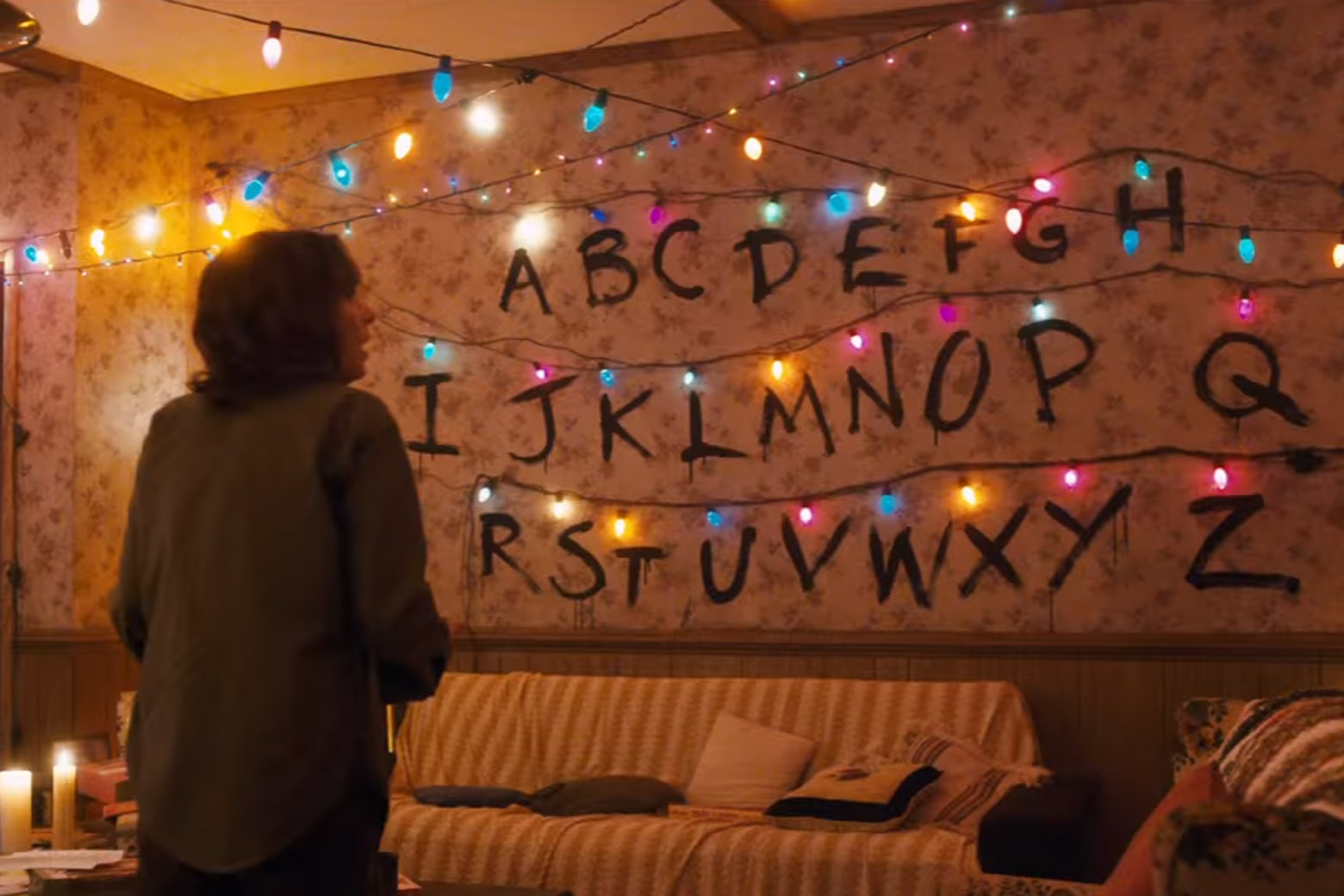
I especially liked the scenes with Winona Ryder’s character Joyce Byers. Watching her figure out that Will could communicate with her through the lights and then stringing up the light wall was probably my favorite part of the series. I haven’t really worked with hardware electrical projects before outside of tutorials but I’d seen a lot of programmable holiday light projects so I figured I could probably build something similar.

The wall that I made is a 13.5”x11” inch piece of cardboard with floral scrapbook paper glued to the front. I poked holes through the cardboard that I pushed the LEDs through and then taped down on the back. I attached a small button switch for easy access to open and close the circuit.
The code runs on an Adafruit Flora running Arduino software and the whole thing is powered by 3 AA batteries.
###Components
- Arduino Flora
- One strand of 12 mm flat weather resistant pixels
- Small weather resistant enclosure
- 3xAA battery pack
- 3 AA batteries
- On/Off switch
- JST 2-pin cable
- Shrink Cable or Electrical Tape
- Cardboard
- Mini plastic zip ties
- Floral paper
- black paint
###Tools
- Soldering Iron
- Wire Cutters
###Assembly
####Step 1: Assemble Display Board
First I figured out how I wanted to display my lights. I decided to string them back and forth and then push the LEDs through the cardboard so only the lights would show. Once I decided where I wanted each light I glued down the paper and cut holes through the card board and paper.
####Step 2: Soldering
Here’s the soldering I did to wire everything up:
- connect yellow wire on strand to d10
- connect green wire on strand to d9
- connect red to vbatt
- connect blue to ground
TEST THE CONNECTIONS AND TEST THE CODE BEFORE SOLDERING FURTHER
- connect red on battery to button
- connect red on button to red on JST 2-pin cable, use the shrink cable or electrical tape to cover any exposed wiring
- connect black on button to black on JST 2-pin cable, use the shrink cable or electrical tape to cover any exposed wiring

###Code
- I had to string the lights in a back-and-forth pattern This means that coupled with a 25 LED light strand indexed at 0, the LED positions are:
A = 24
B = 23
C = 22
D = 21
E = 20
F = 19
G = 18
H = 17
I = 8
J = 9
K = 10
L = 11
M = 12
N = 13
O = 14
P = 15
Q = 16
R = 7
S = 6
T = 5
U = 4
V = 3
W = 2
X = 1
Y = 0
Z = unassigned
- I wrote a small function to randomly display a color on one LED and then reused it to display individual words.
- Another function to light up each LED one-by-one in a different random color. I played around with lighting them all at once and it was jarring so I decided to display one-by-one instead.
- I wrote a loop that runs whenever the circuit is closed. This loops flashes all the lights then flashes a message.
Here’s the code!
###Improvements
I like to call the back side of the panel “the upside down” because it’s such a tangled nightmare:

- Connect the board to wifi and a web server so friends could send messages to the board to be displayed.
- I’d really like to re-solder some of the joints and find a corded phone I can take apart and use as the enclosure.-
- I’ll probably re-do the wall piece as a large display instead of the smaller, more wearable board I have now.
If you order all the materials today you probably have time to build your own in time for Halloween!
comments powered by Disqus